Layout-vs-Schematic (LVS)
Next we run LVS also with Mentor Calibre (i.e., the mentor-calibre-lvs
node). You can run the design up to this node like this:
% cd $top/build
% make mentor-calibre-lvs
Here are the inputs, outputs, and scripts and what they do.
input |
rules.svrf |
An optional file with additional LVS commands to run. |
input |
design_merged.gds |
This must be the same merged GDS that you ran DRC on. The combination of DRC and LVS tells you that the layout is manufacturable (DRC) and that that same layout matches the schematic (LVS) that you run gate-level tests on. If you run DRC and LVS on different layouts, then this semantic link is broken. |
input |
design.lvs.v |
The post-place-and-route gate-level netlist with physical-only cells removed. |
input |
adk |
This node uses the Calibre LVS rule deck from the ADK. |
Open the LVS report to check the comparison result:
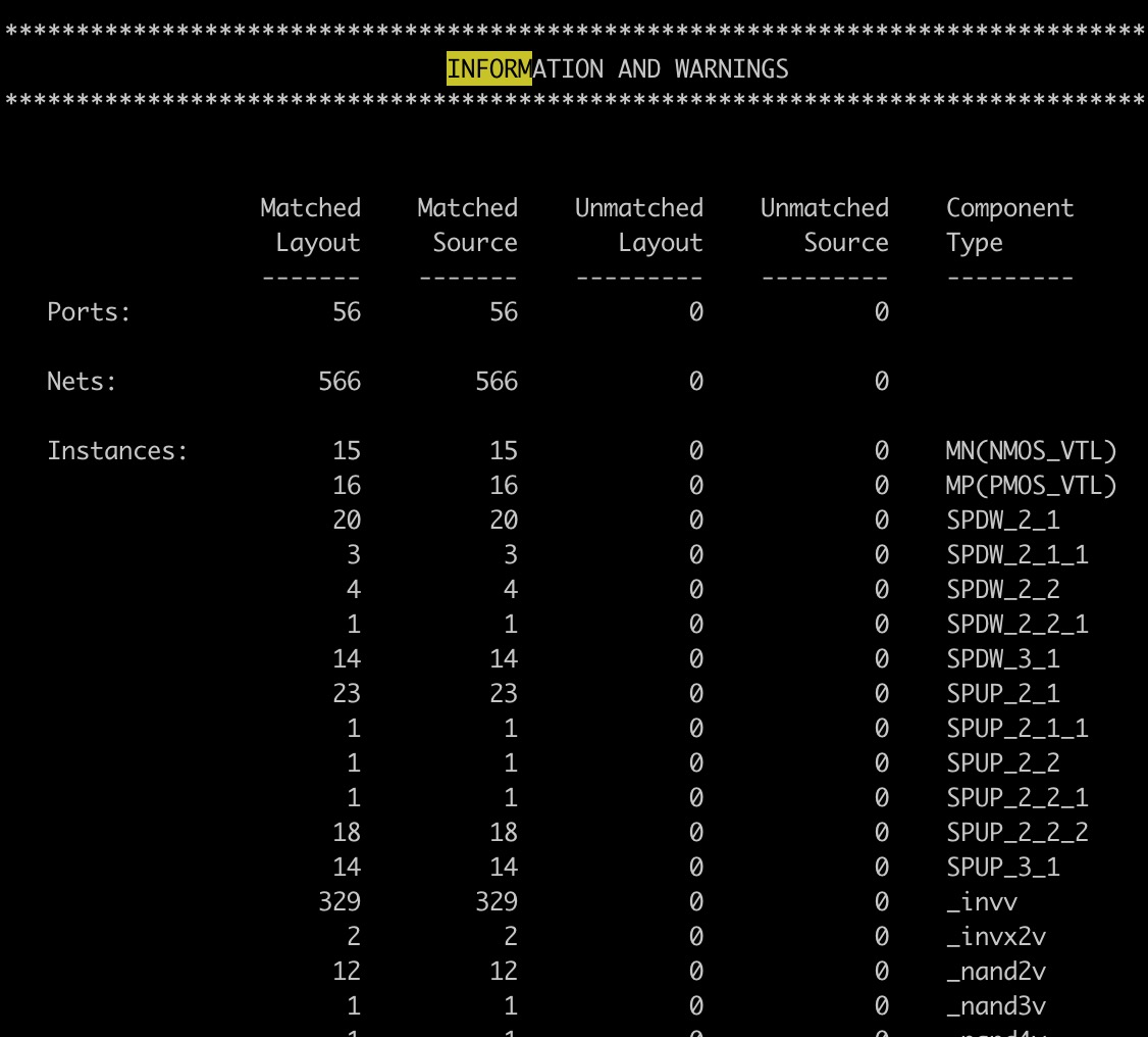
lvs.report– This will have a smiley face at the top if you pass LVS. The most important table to look at in the lvs.report is the “Information and Warnings” table part of the way down. This will show the number of ports, nets, and devices found in the layout and in the source and how the numbers match up.
If you see a mismatch, open the debug target for this node to bring up the GDS viewer GUI (Calibre DESIGNrev). After the layout loads, press $>$ many times to increase the depth and see inside all the cells.
Unfortunately, LVS mismatches are very difficult to debug because of how LVS transforms and squashes transistors together, causing a mismatch in one place to manifest in another. The debug GUI will still be useful to list which nets and ports Calibre thinks are missing.