Design Initialization and Floorplanning
The first step during place and route is called init (i.e., the
cadence-innovus-init node) and reads in the design from synthesis
before executing floorplanning. You can run the design up to the init node
like this:
% cd $top/build
% make cadence-innovus-init
Refer back to Sub-Modular Node Design to see what the inputs, outputs, and scripts are and what they do. Here is a list of scripts you might tweak at this step:
floorplan.tcl– This is where we size the core area (targeting a certain density) and aspect ratio. This is also where we place macros. A reasonable density target is about 75%, and a very aggressive density is over 90%. Aspect ratios that are square are generally preferred over long rectangular ones. Rectangular floorplans place more stress on either horizontal or vertical routing resources and also make it difficult to place macros. Note thatplanDesignis the command that automatically places your macros.pin-assignments.tcl– This is where we use the “editPin” command to spread pins along the sides on specific metal layers. We could also read a pre-saved io file in this script.make-path-groups.tcl– You can create path groups to tell the timing engine to prioritize certain paths that you may find more important than others (e.g., paths to macros). During timing optimization, the tool loops through each of the path groups and tries to fix the worst paths in each group. If there were only a single path group, the tool might never work on paths further down the list that you as a designer know are important. Enough useful path groups have been set for you that you will likely not need to add any more.
Here is a list of checks you will want to run through before moving on to the next step:
reports/preplace.summary.gz– The timing summary report at the end of init assumes no wire delays. This means that the timing reports should look nearly identical to those from synthesis. Therefore, the first thing you should check is that the timing is not be significantly better or worse than in synthesis. When wire delays are factored in, these numbers will only look worse, so the tool should not be trying too hard to meet timing at this point. In particular, there should never be negative slack in this report.
------------------------------------------------------------
          timeDesign Summary
------------------------------------------------------------

+--------------------+---------+---------+---------+---------+
|     Setup mode     |   all   | reg2reg |reg2cgate| default |
+--------------------+---------+---------+---------+---------+
|           WNS (ns):|  0.636  |  0.636  |  1.244  |  0.759  |
|           TNS (ns):|  0.000  |  0.000  |  0.000  |  0.000  |
|    Violating Paths:|    0    |    0    |    0    |    0    |
|          All Paths:|   56    |   34    |    2    |   54    |
+--------------------+---------+---------+---------+---------+
|analysis_default    |  0.636  |  0.636  |  1.244  |  0.759  |
|                    |  0.000  |  0.000  |  0.000  |  0.000  |
|                    |    0    |    0    |    0    |    0    |
|                    |   56    |   34    |    2    |   54    |
+--------------------+---------+---------+---------+---------+

Density: 0.000%
logs/run.log– There should be no errors in the logs. Most possible errors at this stage will be related to reading the technology files and libraries.Check the floorplan in the GUI – Run the debug target on this node and bring up the GUI. GcdUnit does not have any macros, but this is generally the time to make sure that the macros are placed at reasonable locations and orientations (e.g., pins facing the core area, no narrow channels). It can be useful to do a fast prototype of cell placement to see what the design will look like with stdcells. A floorplan mode placement does this by placing cells while ignoring DRCs for speed:
> setPlaceMode -place_design_floorplan_mode true
> place_design
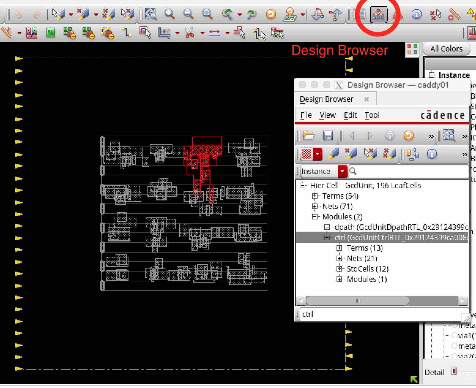
You can also open the
Design Hierarchyviewer and click on a module to see where the stdcells in a particular module were placed. For example, the control module for GcdUnit was randomly placed in a clump near the top in this floorplan-mode prototype placement.